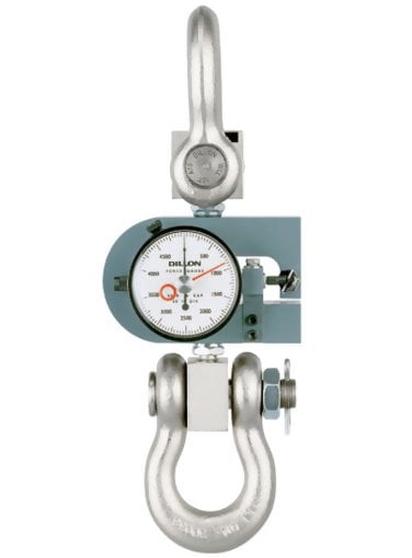
Dillon 30441-0053 X-ST Mechanical Force Gauge with Tension Calibration with Maximum Hand - 10,000lb Capacity

Accuracy is 1%
The Dillon X-ST Mechanical Force Gauge with Tension Calibration is available in seven capacities from 100 lb to 10,000 lb or 25 kg to 5000 kg. Accuracy is 1% of full range. (Note: For applications requiring capacities beyond 10,000 lb or 5000 kg in tension, consider ourrange of dynamometers).
Proven accuracy and ruggedness sets the Dillon X-ST mechanical force gauge apart in the force measurement industry. The "D" shaped deflection beam is the heart of the X-ST. Highly engineered materials with close machining tolerances and proper heat treatment provide optimum strength and spring characteristics.
Kit Contents
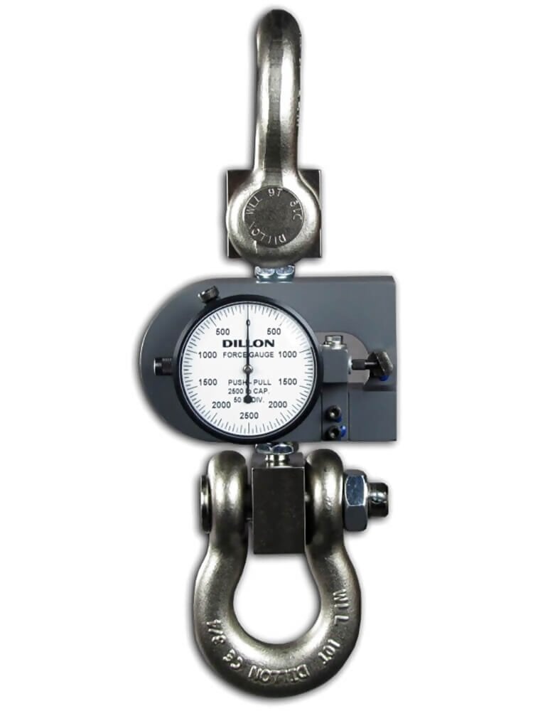
Tension Force Gauges in capacities through 2,000 lb (1000 kg) are supplied with two rod-end connectors. 5,000 and 10,000 lb (5000 kg) capacities are equipped with convenient shackles and pins.
Calibration is available in pounds, kilograms or Newtons.
Specifications
| Accuracy | 1% |
| Operating Temperature | up to 120F (48C) |
| Warranty | 2 Years |
| Overload rating | Accidental overloads up to 30% of capacity can be safely sustained without injury to the dial indicator or deflection beam. All capacities feature a 5:1 design safety factor. |
Options
- Shockless dial indicator for installations involving the sudden application or release of force. (Maximum pointer cannot be supplied with shockless dial indicator)
- Maximum load pointer which remains at peak load until manually reset.
- Zero position on dial may be factory positioned at 12, 3, 6, or 9 o'clock. Standard position is at 12 o'clock.
Force Ranges
| Model | Capacity | Resolution |
| 30443-0044 | 100 lb | 1 lb |
| 30445-0034 | 250 lb | 2.5 lb |
| 30445-0018 | 500 lb | 5 lb |
| 30276-0012 | 1,000 lb | 10 lb |
| 30440-0013 | 2,000 lb | 20 lb |
| 30443-0093 | 50 kg | 0.5 kg |
| 30445-0026 | 200 kg | 2 kg |
Low Beam Deflection
| Capacity | Deflection |
| 50 - 250 lb (25 - 100 kg) | 0.019" |
| 500 lb (200 kg) | 0.016" |
| 1,000 lb (500 kg) | 0.018" |
| 2,000 lb (1,000 kg) | 0.011" |
| 5 and 10,000 lb (2 and 5,000 kg) | 0.010" |
| 25,000 b (10,000 kg) | 0.022" |
When measured across the center of top- and bottom-loading holes
Display Callout
|
|
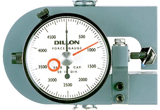
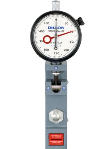
Principle of Operation
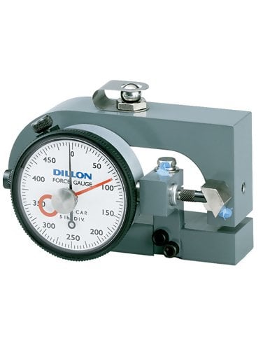
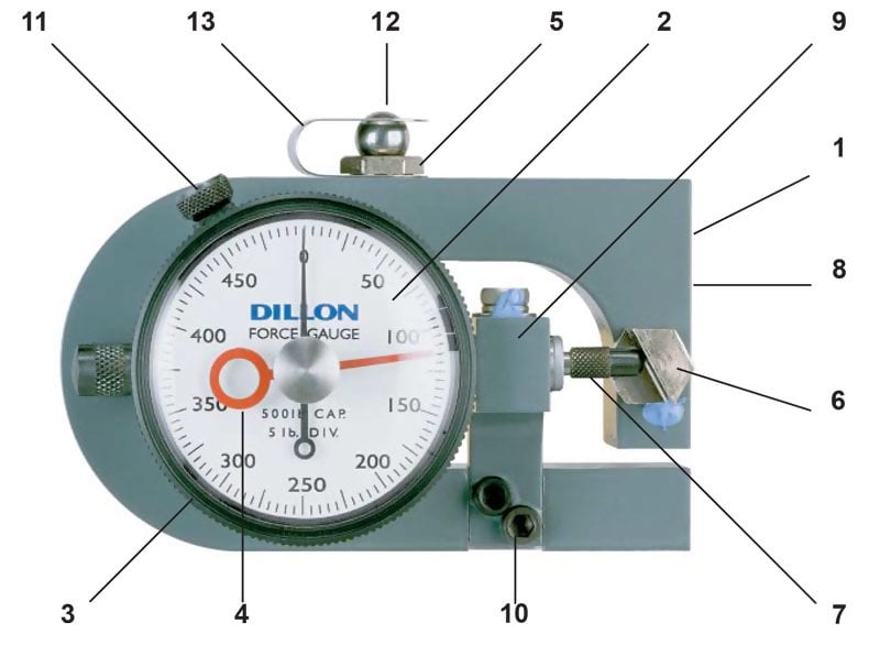
A D-shaped deflection beam is the heart of the Dillon Force Gauge. Machined to close tolerances, beams are heat treated to develop optimum strength and spring characteristics. High-strength aluminum is used in Model X instruments through 500 lb (200 kg). Ranges above this are fabricated from aircraft-quality alloy steel.
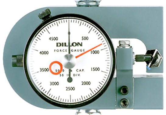
A precision dial indicator is mounted at the null point of the deflection beam. The indicator plunger rests against a slanted anvil at the open end of the beam, as shown in the photo. Under compression loads, the two halves of the beam tend to close. Tension force causes them to move apart. This action pushes the plunger inward, as determined by the slant of the anvil. Readings produced on the dial are in direct relation to applied load.The pointer revolves 360 clockwise under compression or tension forces. Push-pull gauges read half scale (180) clockwise in compression, and counterclockwise, 180 from center zero under tension loads.
Downloads
| Dillon X-ST Mechanical Force Guage with Tension Calibration - Instruction Manual |
| Dillon X-ST Mechanical Force Guage with Tension Calibration - Data Sheet |